WiFi 802.11n Link-level Simulation MATLAB
无意间发现 MATLAB 的官方文档里有许多值得借鉴的仿真 Example。自己一直想弄明白不同 WiFi 协议物理层的仿真步骤以及区别,这里借着 MATLAB 的 WLAN Toolbox 里的案例和大家分享一下物理层的链路级仿真步骤。
源代码链接在此:802.11n Packet Error Rate Simulation for 2x2 TGn Channel - MATLAB & Simulink
大家可以先过一遍官方讲解,再来看这篇文章的讲解。
Waveform Configuration
下面这段代码结合着注释很好理解,定义了波形生成的许多重要参数,下面我来逐一解释一些重要的参数。
(1)wlanHTConfig
HT (High Efficiency) 指的是 802.11n 标准里特定 preamble fields,不同标准的定义不同,像 wlanHTconfig 函数里就定义了 HT Physical Layer 的具体参数。
% Create a format configuration object for a 2-by-2 HT transmission
cfgHT = wlanHTConfig;
cfgHT.ChannelBandwidth = 'CBW20'; % 20 MHz channel bandwidth
cfgHT.NumTransmitAntennas = 2;    % 2 transmit antennas
cfgHT.NumSpaceTimeStreams = 2;    % 2 space-time streams
cfgHT.PSDULength = 1000;          % PSDU length in bytes
cfgHT.MCS = 15;                   % 2 spatial streams, 64-QAM rate-5/6
cfgHT.ChannelCoding = 'BCC';      % BCC channel coding
针对不同的标准,我们所用的数据格式不尽相同,参考下图:
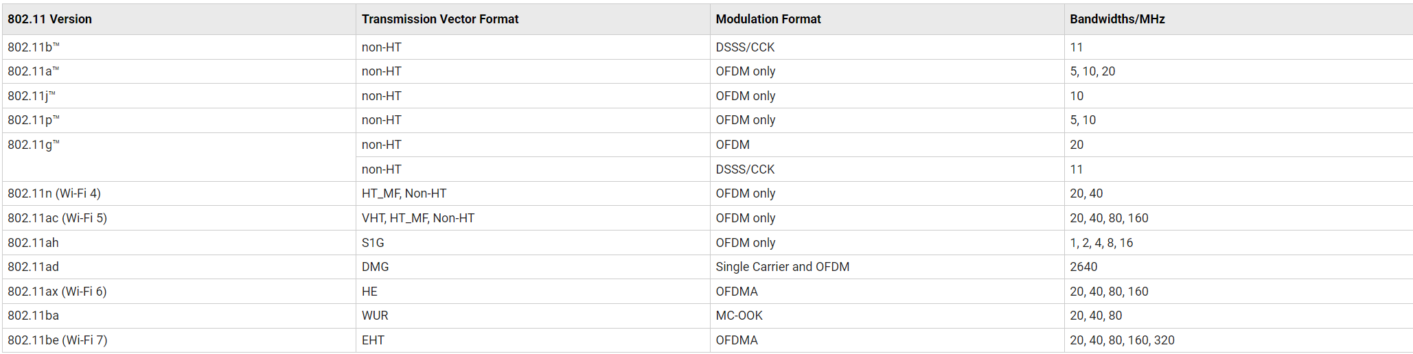
ref: WLAN PPDU Structure - MATLAB & Simulink
Channel Configuration
第二部分的代码也很容易理解,定义了一个更加复杂的信道环境,具体需要修改的函数见:Filter signal through 802.11n multipath fading channel - MATLAB
% Create and configure the channel
tgnChannel = wlanTGnChannel;
tgnChannel.DelayProfile = 'Model-B';
tgnChannel.NumTransmitAntennas = cfgHT.NumTransmitAntennas;
tgnChannel.NumReceiveAntennas = 2;
tgnChannel.TransmitReceiveDistance = 10; % Distance in meters for NLOS
tgnChannel.LargeScaleFadingEffect = 'None';
tgnChannel.NormalizeChannelOutputs = false;
Processing SNR Points
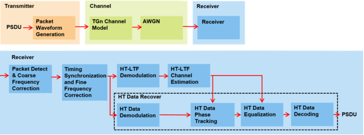
我们先忽略不同的 SNR,重点来看这一部分的代码。刚开始接触时,我发现许多函数(e.g. wlanWaveformGenerator) 里又嵌套了许多,想要寻找具体标准实施细节时,容易被绕晕,对新手不太友好。
 % Generate a packet waveform
        txPSDU = randi([0 1],cfgHT.PSDULength*8,1); % PSDULength in bytes
        tx = wlanWaveformGenerator(txPSDU,cfgHT);

        % Add trailing zeros to allow for channel filter delay
        tx = [tx; zeros(15,cfgHT.NumTransmitAntennas)]; %#ok<AGROW>

        % Pass the waveform through the TGn channel model
        reset(tgnChannel); % Reset channel for different realization
        rx = tgnChannel(tx);

        % Add noise
        rx = awgn(rx,packetSNR);

        % Packet detect and determine coarse packet offset
        coarsePktOffset = wlanPacketDetect(rx,cfgHT.ChannelBandwidth);
        if isempty(coarsePktOffset) % If empty no L-STF detected; packet error
            numPacketErrors = numPacketErrors+1;
            n = n+1;
            continue; % Go to next loop iteration
        end

        % Extract L-STF and perform coarse frequency offset correction
        lstf = rx(coarsePktOffset+(ind.LSTF(1):ind.LSTF(2)),:);
        coarseFreqOff = wlanCoarseCFOEstimate(lstf,cfgHT.ChannelBandwidth);
        rx = frequencyOffset(rx,fs,-coarseFreqOff);

        % Extract the non-HT fields and determine fine packet offset
        nonhtfields = rx(coarsePktOffset+(ind.LSTF(1):ind.LSIG(2)),:);
        finePktOffset = wlanSymbolTimingEstimate(nonhtfields,...
            cfgHT.ChannelBandwidth);

        % Determine final packet offset
        pktOffset = coarsePktOffset+finePktOffset;

        % If packet detected outwith the range of expected delays from the
        % channel modeling; packet error
        if pktOffset>15
            numPacketErrors = numPacketErrors+1;
            n = n+1;
            continue; % Go to next loop iteration
        end

        % Extract L-LTF and perform fine frequency offset correction
        lltf = rx(pktOffset+(ind.LLTF(1):ind.LLTF(2)),:);
        fineFreqOff = wlanFineCFOEstimate(lltf,cfgHT.ChannelBandwidth);
        rx = frequencyOffset(rx,fs,-fineFreqOff);

        % Extract HT-LTF samples from the waveform, demodulate and perform
        % channel estimation
        htltf = rx(pktOffset+(ind.HTLTF(1):ind.HTLTF(2)),:);
        htltfDemod = wlanHTLTFDemodulate(htltf,cfgHT);
        chanEst = wlanHTLTFChannelEstimate(htltfDemod,cfgHT);

        % Extract HT Data samples from the waveform
        htdata = rx(pktOffset+(ind.HTData(1):ind.HTData(2)),:);

        % Estimate the noise power in HT data field
        nVarHT = htNoiseEstimate(htdata,chanEst,cfgHT);

        % Recover the transmitted PSDU in HT Data
        rxPSDU = wlanHTDataRecover(htdata,chanEst,nVarHT,cfgHT,...
            "LDPCDecodingMethod","norm-min-sum");

        % Determine if any bits are in error, i.e. a packet error
        packetError = any(biterr(txPSDU,rxPSDU));
        numPacketErrors = numPacketErrors+packetError;
        n = n+1;
1.wlanWaveformGenerator
如果你在 MATLAB 里点开这个函数的源文件,你会发现是一个特别复杂的函数。我们来回顾一个简单 OFDM 系统的框图:
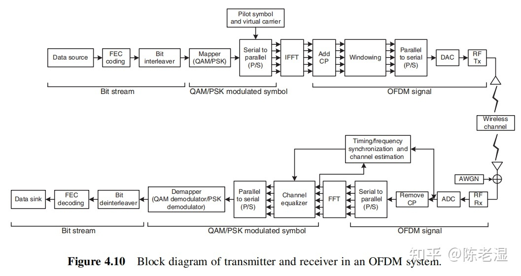
这里的 wlanWaveformGenerator 一个函数就实现了上图的上半部分的所有功能,并且还实现了各个标准里各种复杂的帧格式和细节设定。
在 802.11n 标准下,我们用的是 HT 的数据格式,我们就去源文件里找和 HT 相关部分即可,先忽略其余部分。

大家可以对应左边的行号去找到 wlanWaveformGenerator.m 文件里的相关部分,然后逐一去理解和比对。
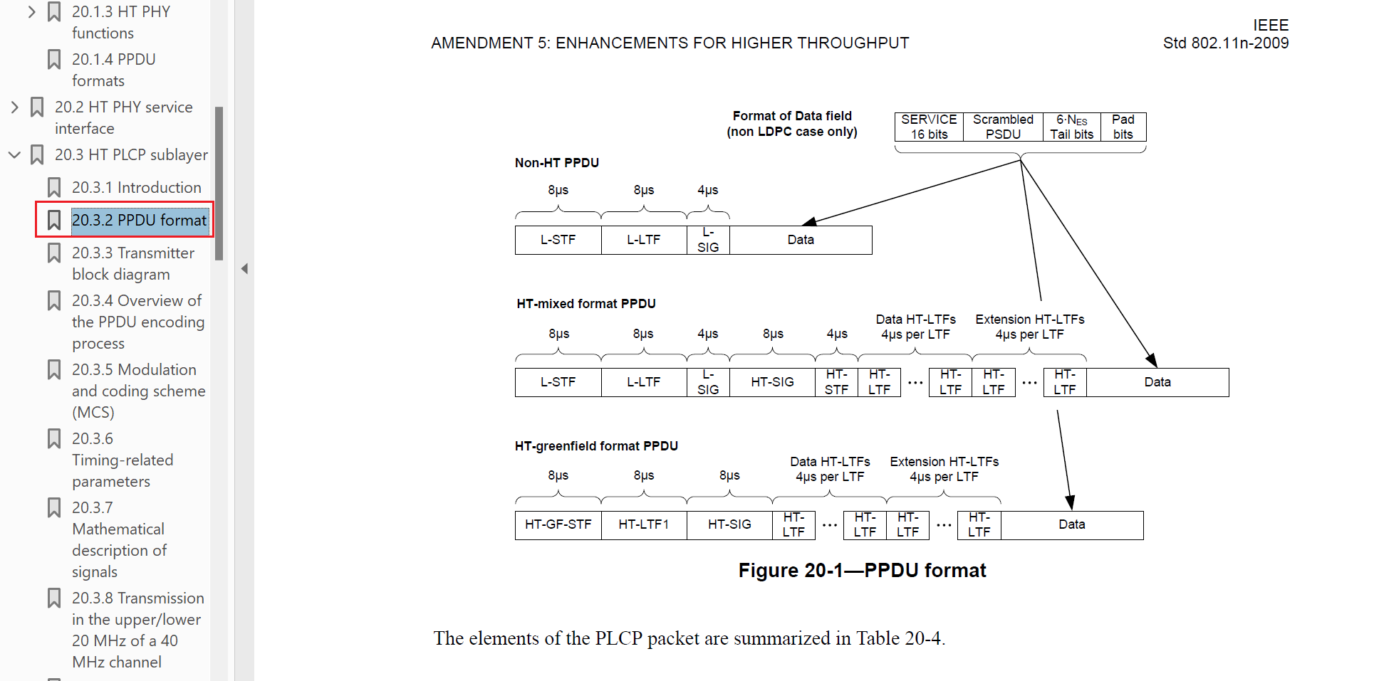
这部分代码的作用也很明显,用来生成 premeable fields,具体的细节大家可以参考 802.11n-2009 版本的标准(对应部分在下图)。很明显,这里实现的时 HT-mixed format PPDU 的格式。
这里我来进行一个概念解析,初学者接触到许多缩略名词,很容易摸不着头脑,比如 PSDU,PLCP,PPDU 这三者究竟有什么区别?
(1)PSDU
PSDU (Physical Layer Service Data Unit)实际上就是我们实际要传输的数据,它源自 MAC 层的 data frame,并且经过一系列处理,比如说 data encoding, fragmentation 等操作。
(2)PLCP(Physical Layer Convergence Procedure Header)
这里偷个懒,直接截取英文版本,中文翻译过来反而不太容易理解。
Its main purpose is to prepare the data frames from the MAC (Media Access Control) layer for transmission over the wireless channel. The PLCP header carries essential information that helps the receiver synchronize and interpret the incoming data correctly. This information includes the modulation and coding scheme (MCS), data rate, and length of the data frame.
举个例子,在 HT-mixed format PPDU 的 PLCP 又分为不同的小部分,总共分为三类:STF,LTF,SIG,这里简单介绍一下它们三个分别的作用。
L-STF(Legacy Short Training Field)有两种作用:
- Synchronization(同步): The L-STF helps the receiver synchronize its timing with the incoming signal. It consists of a known and well-defined pattern that the receiver can detect and use as a reference to synchronize its clock with the transmitter's clock.
- Coarse Frequency Offset Estimation(频偏估计): The L-STF assists the receiver in estimating the coarse frequency offset between its local oscillator and the transmitter's oscillator. Accurate frequency synchronization is essential for proper signal demodulation.
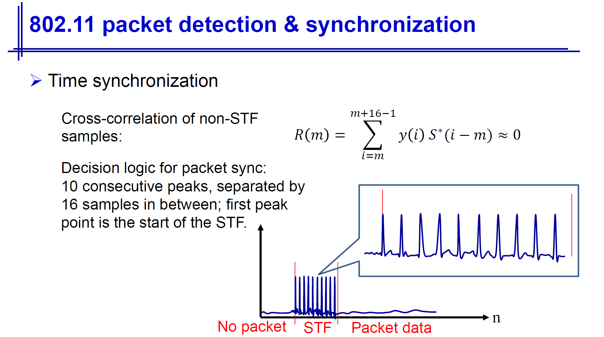
如下图所示,如果我们对于接收到的信号进行 cross-corrleation,下图里所示的波形,当出现这样的形状时,代表我们检测到了信号。(其中 是我们已知的 STF 训练序列)。
L-STF(Legacy Short Training Field)作用如下:
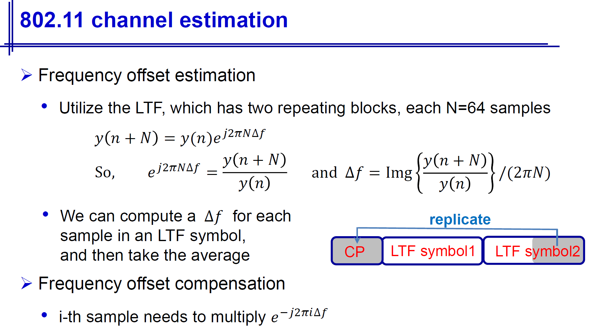
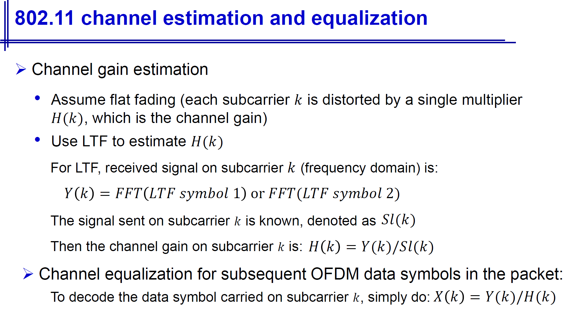
The L-LTF follows the L-STF in the PLCP header and is primarily used for channel estimation. It helps the receiver estimate the characteristics of the wireless channel, such as multipath, fading, and other impairments. The L-LTF is designed to be longer in duration than the L-STF, providing more time for the receiver to analyze the channel response.
L-STF 的作用也如下图所示,能用于信道估计和粗频偏估计。
SIG Field 定义的参数就很多元化了。举个例子,比如说对于 HT-SIG Field,标准里的描述是:
The HT-SIG is used to carry information required to interpret the HT packet formats.
包含的信息有 MCS level,CBW,STBC,FEC coding 等等,大家可以自行去标准里查看细节,这里就不赘述了。
接下来,我们再来看另外一个重要部分:
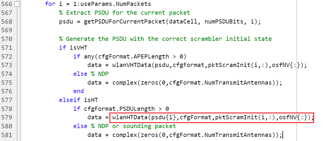
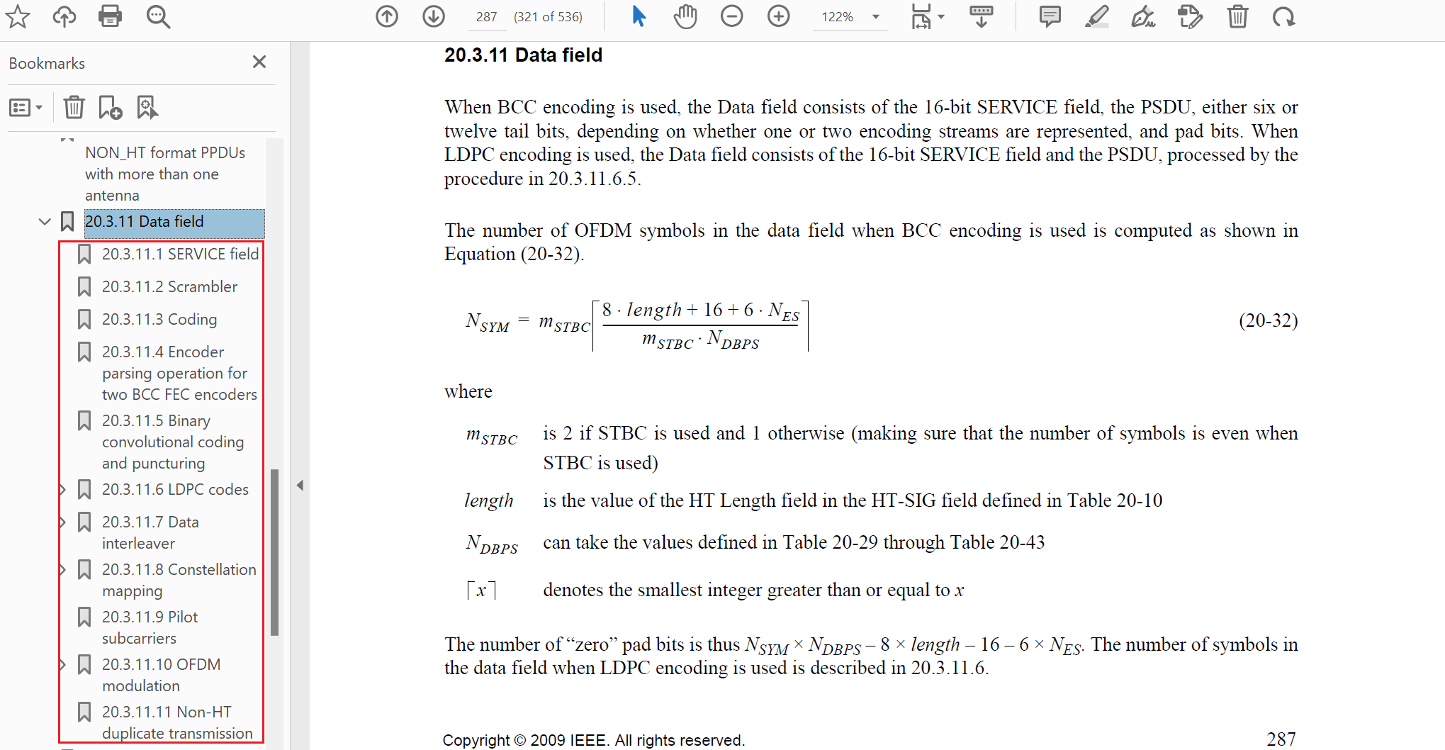
wlanHTData 函数里也有非常多的细节,整体大框架和 802.11n-2009 标准里 20.3.11 Data Field 的流程类似,感兴趣的朋友自行去翻阅细节。
这里我大致介绍一下每个步骤的作用,便于从整体理解为什么要设计这个模块。
- Scrambler: Scrambler 原理是生成一个伪随机序列(收发两端都知道),然后用这个序列和发送的数据进行异或,从而给我们发送的数据添加一定的随机性。这样的好处是避免出现一长串的 0 或者 1 序列,而这样的序列会影响到接收端的同步。
- Coding:802.11n 里支持 BCC 和 LDPC 编码方式,总的来说,LDPC 性能更优,但更新的标准里都兼容了 BCC 的编码方式。
- Interleaver(交织器): interleaves the bits of each spatial stream (changes order of bits) to prevent long sequences of adjacent noisy bits from entering the BCC decoder. Interleaving is applied only when BCC encoding is used.
- Constellation mapper: maps the sequence of bits in each spatial stream to constellation points (complex numbers).
- OFDM modulation:这个就不多说了,具体实现也有很多繁复的细节,大家可以自行去 wlanHTData 函数里看具体的实现过程和参数设置。
2.wlanPacketDetect & wlanCoarseCFOEstimate
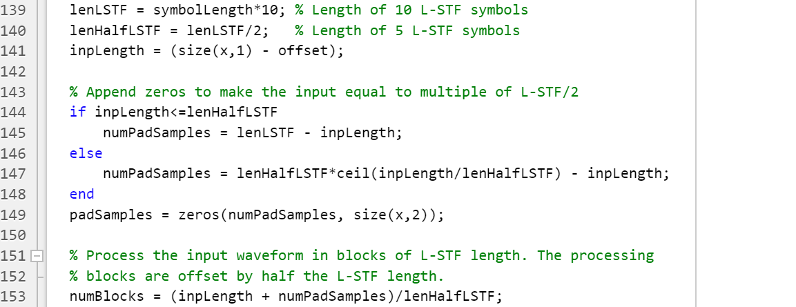
中间我省略了两步,分别是信号经过 TGn 信道和添加 AWGN 噪声,这两步没什么理解难度,就不多说了。
首先我们来看看这个函数的定义:
STARTOFFSET = wlanPacketDetect(X, CHANBW) returns the offset from the start of the input waveform to the start of the detected preamble using auto-correlation. Only OFDM modulation is supported.
下图是 wlanPacketDetect.m 的部分截图。还记得之前说过的 L-STF 序列嘛?在进行 Packet Dectection 时就用到了,这里实现方法和前面所说略有不同,但整体原理是一致的。
另外一个函数值得一讲的函数是 wlanCoarseCFOEstimate,先来看函数的定义:
FOFFSET = wlanCoarseCFOEstimate(IN,CHANBW) estimates the carrier frequency offset FOFFSET in Hertz using time-domain L-STF (non-HT Short Training Field). The short length of the periodic sequence within the L-STF allows coarse frequency offset estimation to be performed.
这两个 offset 区别通过定义大家也应该清楚了,第一个STARTOFFSET = wlanPacketDetect(X, CHANBW) 返回的是 rx 接收到的信号的开头和实际用 L-STF 检测到的开头之间的偏差。而第二个FOFFSET = wlanCoarseCFOEstimate(IN,CHANBW) 估计的是子载波的频偏,一般是因为像 Doppler Effects,oscillator inaccuracies 等原因,导致收发两端频率不同步。
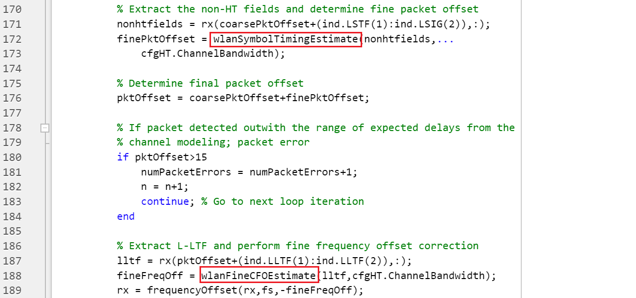
3.wlanSymbolTimingEstimate& wlanFineCFOEstimate
上一部分的两个 offset 估计都是粗略的估计,简单来说,只能知道大概的偏移范围,但并不是准确的估计。
这里笔者觉得疑惑的是,在 wlanSymbolTimingEstimate.m 文件里用到了 L-LTF 来完成 fine packet offset estimation,但以前接触 L-LTF 的作用往往是频偏估计以及信道估计,并不涉及 packet offset estimation 的功能,这里留下一个疑问,如果有知道朋友可以帮忙解答一下。
4.剩余部分
       % Extract HT-LTF samples from the waveform, demodulate and perform
        % channel estimation
        htltf = rx(pktOffset+(ind.HTLTF(1):ind.HTLTF(2)),:);
        htltfDemod = wlanHTLTFDemodulate(htltf,cfgHT);
        chanEst = wlanHTLTFChannelEstimate(htltfDemod,cfgHT);

        % Extract HT Data samples from the waveform
        htdata = rx(pktOffset+(ind.HTData(1):ind.HTData(2)),:);

        % Estimate the noise power in HT data field
        nVarHT = htNoiseEstimate(htdata,chanEst,cfgHT);

        % Recover the transmitted PSDU in HT Data
        rxPSDU = wlanHTDataRecover(htdata,chanEst,nVarHT,cfgHT,...
            "LDPCDecodingMethod","norm-min-sum");
余下的部分感觉没什么可细讲的了,解调-信道估计-噪声估计-译码的经典步骤,如果深入进每个函数,确实有不少值得细讲的地方,大家可以重点关注 wlanHTDataRecover.m 源文件,基本上是 wlanWaveformGenerator.m 里面步骤的反向操作,用来得到传输的数据。
小结
之前我自己的课程作业有实现过 802.11a 链路级仿真,但是在手写 802.11n 的链路级仿真上还是有点有心无力。毕竟 802.11n 标准相比于 802.11a 增加太多的实现细节,从头手写还是有点太浪费时间。借着 MATLAB 提供的 Example,认真地过了一遍 802.11n 仿真里的函数,收获颇丰,原来看着头大的标准文件,现在读起来也没从前那么吃力了。
这里建议大家去 IEEE 上下载对应的标准文件,然后结合着代码去研究标准里的相关部分,就很容易理解了。